Tuesday, February 16, 2016
Tuesday, February 2, 2016
Sunday, January 31, 2016
Modeling with edit mode Mario

Thursday, January 28, 2016
Adding faces to model
- Another way to model 3d is using faces.. added

- We will learn to make Mike from Mosters Inc. Prefferably we need a side profile image but until I find one this will suffice.
-Download Mike's image

-First step is to add the image as a reference just like we did with the robot.
-Set the image reference to be viewed in Front Orthogonal.
-Now go to the front orthogonal view to see the reference (press 1 in the numpad, if you still dont see the image you must be in perspective mode so press 5)
-Move the reference image until it looks like its centered in the origin lines.
-Now add a plane, rotate the plane and place it in right on top of the mouth
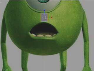
-Select the plane and go to "Edit Mode" and in edit mode choose "Face Mode"
-Once in edit mode on the left panel select tools and click "loop cut and slide"
-Move the mouse to the top middle area of the plane until you see a line and click twice without moving it, this will divide the face in two
-Select the left face and delete it.
-Now while in "Edit Mode" go to the modifiers menu (the little wrench icon)
-And select Mirror, in the mirror preferences check the "clipping" box.
- And the icon to show the modifier in edit mode, looks like this:
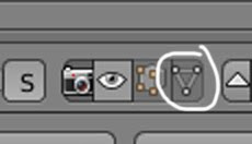
-Now we have mirror mode so we can start creating faces. we will start extruding segments so go to segment mode and select the side segments, to extrude use the "e" key, and move/rotate/scale the segments until they look correct.
-Useful shortcuts:

Thursday, January 21, 2016
Jan 22
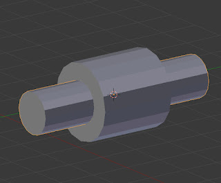
- Next we will add a cable made with a curve modifier and finally pose our model.


- We first create a cylinder that is long and thin like this one.

Then place one end of the cylinder into the connection behind the robot.

- We add more detail to the cable cylinder. First change to "edit mode" then click "subdivide" 6 times.
- Go back to "object mode"
- Add a path, in the lower menu Add->Curve->Path, Press "z" to see the wireframe and move the path to the connection at the back of the robot like this:

- The path is the thin yellow line.
-Now we will add a "curve" modifier to the cylinder.
- Set the object in the modifier to the path, is the cylinder moves, place it back to where it was.
- Now select the path and go to "edit mode".
-Select the vertex in the curve that is away from the robot then use Ctrl + left click to start adding vertices and shaping the cable:

-Then move the vertices until the cable looks the way you want it.
-Go back to object more and place the plug in the other end of the cable.

Jan 22 Hierarchy and posing
-We going to add hierarchy to our robot model so we can pose him, the idea is that every part of the robot can have a parent, this parent affects the child when its transformed, for example we can have a forearm to be the child of an elbow and the elbow the child of the arm, this way when we rotate the arm the elbow and forearm will follow, when we rotate the elbow only the forearm will follow, etc.
-To link two objects as parent and child first we need to select the child, then holding the shift key we select the object we want to be a parent.
- We then press Ctrl+P and then the click on "Object"
- That is all, now if we move the parent we will move the child as well
- So we can rotate shoulders, knees, etc to pose the robot like this:
-We can do this for all parts, all ending on the torso of the robot, so the foot connects to the lower leg, the lower leg to the knee, the knee to to the upper leg, etc until we get to the torso. We do the same for all limbs as well as the head (hat to head, head to neck, neck to torso)
-At the end the torso can be used to transform the entire robot.
Here is a link to the robot up to this point.
-To link two objects as parent and child first we need to select the child, then holding the shift key we select the object we want to be a parent.
- We then press Ctrl+P and then the click on "Object"
- That is all, now if we move the parent we will move the child as well
- So we can rotate shoulders, knees, etc to pose the robot like this:

-We can do this for all parts, all ending on the torso of the robot, so the foot connects to the lower leg, the lower leg to the knee, the knee to to the upper leg, etc until we get to the torso. We do the same for all limbs as well as the head (hat to head, head to neck, neck to torso)
-At the end the torso can be used to transform the entire robot.
Here is a link to the robot up to this point.
Jan 22 Modifiers
-Almost forgot about Modifiers. In this case we will use them to create a claw
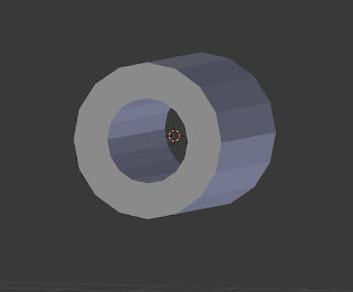
-To do this we need two cylinders, we will use one cylinder to remove the inside of the other, so we need to scale them and place them like this.
- To apply the modifier we select take a note of the inside cylinder's name, lets say its name is cylinderA
-We select the outside cylinder and click on the modifier icon and choose "Boolean":

-In the panel that shows up in the right side of the screen, select "difference" for operation and the Object cylinderA (remember the name depends on what you have, it will not be cylinderA)
- Then click apply.
- Delete the inside long cylinder and you will end up with this:
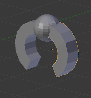
- Now we can use a cube and a modifier on this object to end up with half a claw like this:
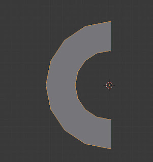
-We can duplicate/rotate this to create a claw.
-To do this we need two cylinders, we will use one cylinder to remove the inside of the other, so we need to scale them and place them like this.

- To apply the modifier we select take a note of the inside cylinder's name, lets say its name is cylinderA
-We select the outside cylinder and click on the modifier icon and choose "Boolean":
-In the panel that shows up in the right side of the screen, select "difference" for operation and the Object cylinderA (remember the name depends on what you have, it will not be cylinderA)
- Then click apply.
- Delete the inside long cylinder and you will end up with this:

- Now we can use a cube and a modifier on this object to end up with half a claw like this:

-We can duplicate/rotate this to create a claw.

Jan 22
We will work on the plug and creating parent child relations for posing the model.


- For the plug we start setting this image for the top and front orthogonal views.

-One setup we can start by creating the top of the plug create a cube and place it at the top of the plug. Using the Edit Mode create a side of the top as in the images.

-To get the top view to work you will have to move the image to match the position of the box

-Use "Edit Mode" to scale the vertices clicking "vertex mode"


-Now we are going to extrude a face, use face mode
-Select the inside side face and on the tools panel on the left select "extrude region"

-Translate it until it looks correct.


-Now we extrude the same side face one more time

- And scale the face so it looks the same as the other side.

- Now duplicate the object just created and put it below the original one, scaling it as well so it fits the reference image.


-Go to edit mode and extrude and scale until you end up with this:

-We add a small cylinder on the bottom for the cable connection.
-Now for the plug connections we will create a cylinder and a cube and scale them and place them to end up with this:

-We use the a boolean modified to merge them, then we use a smaller cylinder to make a hole at the top area to end up with this:

-Now we duplicate it and scale and position them on the plug using the reference images.


-And that is our plug.

Monday, January 18, 2016
Jan 15 work
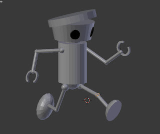
The goal of the class was to end with a basic robot like the following.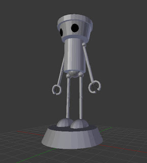


To get this result we start by adding a reference image to the front orthogonal view with these steps:
-Click the plus "+" sign at the top right side of the screen, next to the right panel

-A new panel will show up, scroll down that panel until you find "Background Images" and expand it with the small triangle next to it.
-Click on "add image" them "open", choose the image chibifront.jpg (the second image in the prev post)
- Where it says "axis" choose "front"
- Now to get a front view from the modeling space press 1 in the numpad, if you don't see the image, probably means you are in prespective mode, press 5 in the numpad to toggle to orthogonal mode and you should see this.

- Some useful short-cuts for cameras are 1 = front 3=right 7=top and 5=toggle perspective/orthogonal
-The idea now is to start adding cylinders and spheres (from the create tab at the left side) and using scale/rotate/move to model them into shapes that we can use for the reference, for example adding the robot's hat:

- There are some items that cannot be done by using scale/rotate/move, for example the angled sides of the face, for this we need to edit the cylinder we will use for its face.
- To edit an object's geometry we go into what is called "edit mode", currently we are in "object mode", look at the bottom left-middle area there is a drop list that says "object mode".

- First create a cylinder for the face and scale it to fit the reference.
- With the new face cylinder selected change "object mode" to "edit mode"
- Now you can change the elements of the cylinder, these include vertices, segments and faces.

-We will reduce the size of the bottom face of the cylinder to create the angled cylinder, first select the "edit face" button.

- Move the camera until you get a bottom view (holding down the wheel button) and the select the lower face (right button click).

- Go back to front view (1) then press "scale" from the tools panel (left side), move the mouse to scale the bottom face until it matches the reference.

- Now change from "edit mode" to "object mode" so you can keep adding/creating/modifiying other objects.
- Using this basic techniques we can en up with a robot with no feet and no claws.

- Next class we will:
- Use "boolean modifiers" to create the feet and claws.
- Use face extrude to add details and create the the robot's plug (refer to previous post)
- User hierarchy to create parent child relations so we can easily pose our model
Thursday, January 14, 2016
Jan 15 - Project Idea
3D Model idea for this project at the moment is Chibi robot


We will start modelling it is a default pose, similar to the front image (second one).
Here are some views of the plug as well.

This should be the first pass result with no plug

Here are some views of the plug as well.

This should be the first pass result with no plug

Subscribe to:
Posts (Atom)